Moisture Analysis Comparison: Dew Point Accuracy
6th May•10 min read
Semiconductor cleanroom compressors and ISO Class 1 compressor comparison starts with one non-negotiable fact: a single micrometer-sized particle can destroy a microchip in production. Unlike general industrial air, the compressed air delivered to semiconductor fabrication bays must achieve extreme purity standards, and that purity is a system outcome, not a single component's promise. Cleanroom compressors sit at the foundation of that system, but they're only as effective as their filtration stages, drying capacity, and pressure regulation architecture.
I've spent years helping shops dial in clean, dry air for finishing work, and the principle I've seen repeat across sectors holds here: when you measure pressure at the actual point of use and validate dew point, you eliminate the guesswork that costs time and defects. In semiconductor operations, that discipline isn't optional, it is survival. This guide compares ISO Class 1 compressor setups so you can understand the architecture, verify vendor claims, and architect a system that delivers spec-grade air, repeatably.
Semiconductor manufacturing demands the highest level of compressed air purity, defined by the ISO 8573 air purity standard (ISO 8573-1:2010), the international standard for compressed air quality. ISO Class 1 air represents the pinnacle of purity and sets the baseline for ultra-critical semiconductor processes.[4]
ISO Class 1 compressed air allows a maximum of 0.1 particles per cubic meter at 0.1 micrometers or larger, and zero particles at 0.5 micrometers or greater.[4][6] To contextualize: that's roughly 10 particles in an Olympic swimming pool. Wafer fabrication, photolithography, and ion implantation are processes where a single airborne contaminant can render a die non-functional, making this specification non-negotiable.[5]
Comparing ISO classes reveals a steep performance gradient. ISO Class 2 allows 100 times more 0.1 µm particles than Class 1; ISO Class 3 (1,000 particles/m³) is used only for the most demanding semiconductor wafer processes. Class 5 (100,000 particles/m³) is typical for high-volume fabrication bays, yet still requires unidirectional airflow and laminar air management.[3][5]
Particles are only half the contamination story. Pressure dew point (PDP) and residual oil content define the other critical dimensions.
ISO Class 1 demands a pressure dew point ≤ -70 °C, ensuring that even trace moisture cannot condense in process lines or on wafers.[4] If you're deciding between refrigerated, desiccant, or membrane options to reach this target, compare technologies in our air dryer guide. Any water droplet or hygroscopic salt residue can trigger corrosion in precision tooling or cause ionic contamination on silicon surfaces, a silent killer in defect rates.
Oil content must not exceed 0.01 mg/m³.[4][6] Semiconductor equipment operates at extreme temperatures and uses vacuum systems where any hydrocarbon film acts as a contaminant vector. Microchip defects traced to oil residue often don't appear until final test, compounding cost.
ISO 8573-1 notation uses three digits: particle class, water class, oil class. For semiconductors, the full specification is typically ISO Class 1:2:1 (particles:water:oil), though the most demanding ultra-large-scale integration (ULSI) fabs specify Class 1:1:1 to eliminate all margin for error.[4][6]

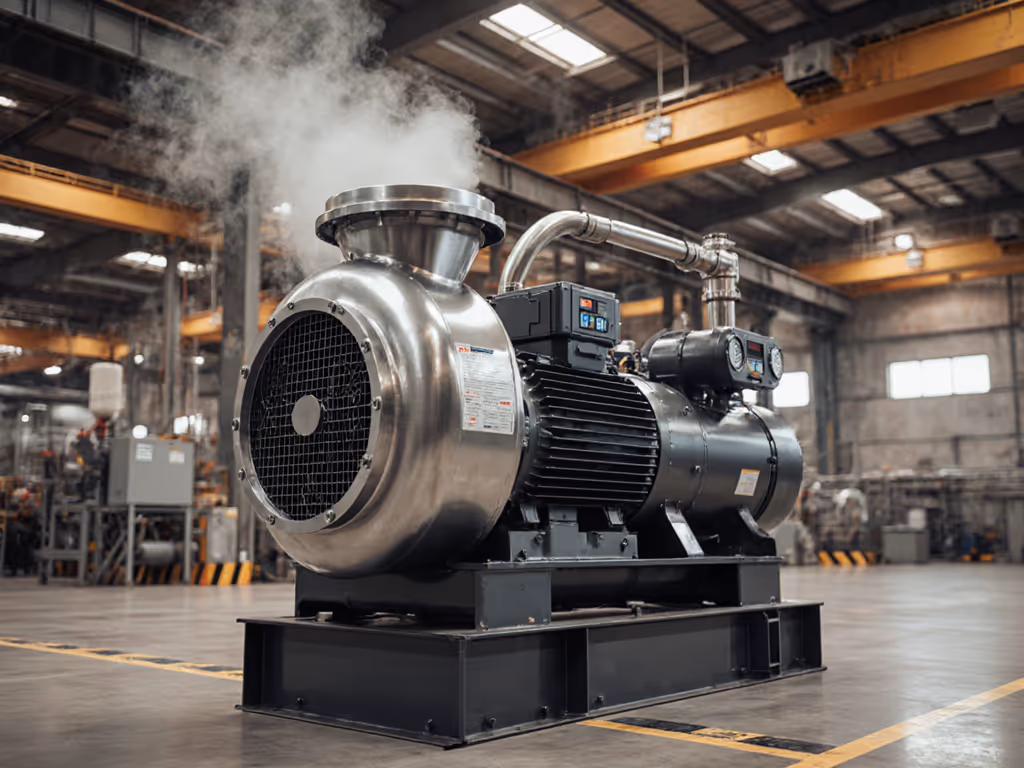
The compressor is the air source, but semiconductor-grade systems differ fundamentally from general industrial units in three ways: oil-free design, staging for efficiency, and integrated aftertreatment.
Oil-free rotary screw compressors are the standard for semiconductor applications. Lubricated compressors inherently carry oil vapor that, even after standard coalescent filters, leaves trace residue. Downstream particulates and moisture removal become more expensive and less certain.
ISO Class 0 (Atlas Copco terminology) specifies that air originates from an oil-free compressor at the source, not from oil-free certification achieved through additional filtration.[4] This distinction is critical: true oil-free design eliminates the contamination pathway rather than trying to filter it downstream.
Oil-free units operate at higher discharge temperatures and require robust aftercoolers and desiccant dryers. The capital cost is higher (typically 20-40% above lubricated models), but the total cost of ownership favors oil-free systems when you factor in filter replacement frequency, drying performance, and defect rates.
Semiconductor fabs typically operate two-stage oil-free compressors with intercooling. Each stage reduces the compression ratio, lowering discharge temperature and improving volumetric efficiency. Lower discharge temperature means:
High-capacity fabs may employ centrifugal compressors in series with rotary screws, but that topology is typical only in large-scale operations with continuous, predictable demand.
Clean, dry, stable air makes finishes look inevitable, and in semiconductor fabs, clean, dry, stable air makes chip yields inevitable. The compressor itself delivers perhaps ISO Class 4 or 5 air (500+ ppm particles, high moisture). Three sequential treatment stages are required to reach ISO Class 1.
The first aftercooler and coalescent filter removes large particles (1-10 µm), liquid aerosols, and oil vapor. A typical specification is 5 µm absolute (or finer, down to 0.3 µm) to catch corrosion products and compressor wear debris before it reaches desiccant media.
Coalescent filters trap moisture by creating larger droplets that drain via an automatic drain valve. However, coalescence alone does not remove dissolved water vapor, only its liquid form.
Desiccant adsorption dryers are mandatory for ISO Class 1. These units use silica gel or molecular sieve cartridges that adsorb water molecules directly from compressed air, achieving pressure dew points as low as -70 °C or colder.
Desiccant dryers operate in one of two modes:
For semiconductor plants, heated desiccant dryers with cycling or flushing (dual-tower) designs are standard. Dual-tower systems isolate the regeneration cycle from the drying cycle, ensuring zero dew point excursions during switchover.
After drying, a 0.01-0.1 µm absolute filter (often called a "sterile" or "absolute" filter) removes any desiccant dust, rebound moisture, or microbial contamination. For designing a full treatment train that sequences prefilters, dryers, and finals without excessive pressure drop, see our multi-stage filtration comparison. Glass-fiber or membrane media rated to ISO Class 1 performance is standard. These filters have high surface area and low differential pressure to minimize back-pressure on the dryer.
A lesson I learned from a body shop that struggled with fish-eyes and orange peel: they measured pressure at the tank (100 psi) and assumed that's what the spray gun received. We measured at the trigger and found 28 psi. The hose was corroded internally, the regulator was underrated, and moisture from the lines was contaminating the finish. One desiccant tower, fresh hose, and a regulator mounted at the application point transformed the results: rejects fell by ninety percent in one week.
Semiconductor systems face the same principle, scaled. Pressure regulators must be sized for the flow requirement and positioned as close to the point of use as practical, for three reasons:
Vendor datasheets specify compressor discharge pressure, but the ISO Class 1 standard's purity metrics assume air measured at the point of end use, not at the tank. Verify this distinction in vendor documentation and validate pressure drop in the field.
Leading manufacturers (Atlas Copco, Ingersoll Rand, Gardner Denver, Festo) each offer semiconductor-grade compressor packages. Comparison on these key parameters will guide selection:
| Specification | Minimum Semiconductor Requirement | Impact on Yield/Cost |
|---|---|---|
| Compressor Type | Oil-free, two-stage, rotary screw | Eliminates oil contamination at source; enables PDP ≤ -70 °C |
| Aftercooler | Water-cooled or air-cooled, optimized for 10-20 °C delta-T | Reduces inlet temperature to dryer, improves moisture removal efficiency |
| Coalescent Filter | 0.3–1 µm, automatic drain, bypass valve | Protects desiccant media; extends cartridge life |
| Desiccant Dryer | Heated, dual-tower or cycling, digital monitoring | Achieves and holds PDP ≤ -70 °C; alerts on saturation |
| Final Filter | 0.01-0.1 µm absolute, membrane media | Meets ISO Class 1 particle limit; no fiber shedding |
| Monitoring | Differential pressure gauges, dew point sensor at outlet | Validates ongoing compliance; early detection of degradation |
Beyond components, total system volume and distance from compressor to fab matter. Small, distributed skid-mounted systems near point-of-use are more responsive and reduce dead-leg risk (sections of pipe where stagnant air can stratify and re-humidify). Large centralized compressor rooms with long piping demand higher safety margins on dryer capacity and more vigilant drain maintenance.
Semiconductor fabs typically operate compressor systems continuously or with predictable on/off cycles tied to process schedules. Reliability requirements are unforgiving: a single compressor failure during a wafer run can scrap wafers in process, costing hundreds of thousands of dollars per hour.
Redundancy is standard in high-volume fabs. Two or more compressor systems run in parallel, each sized to meet demand independently. One compressor can be down for maintenance while production continues. Check-valves prevent backflow; pressure sequencers ensure load balancing.
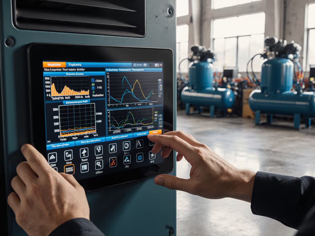
Monitoring and predictive maintenance use:
Vendors such as Atlas Copco and Ingersoll Rand now offer IoT-enabled monitoring packages that log these parameters and alert service teams to degradation, critical for predictive maintenance in mission-critical semiconductor environments.
| Factor | High Capital Cost, Lower Operating Cost | Lower Capital, Higher Operating Cost |
|---|---|---|
| Compressor Type | Multi-stage oil-free, variable displacement | Single-stage, load-unload control |
| Dryer | Heated dual-tower, low purge loss | Heatless, simple but high purge (10-20% air loss) |
| Monitoring | Integrated sensors, networked | Manual checks, pressure gauges only |
| Service & Spares | Longer intervals, fewer spare parts stocked locally | Frequent cartridge changes, higher consumables cost |
| Total 5-Year Cost | Lower (lower electricity, fewer filter changes) | Higher (energy waste, frequent consumables) |
Semiconductor fabs almost always favor the left column. Higher upfront investment pays for itself within 3-5 years through energy savings and reduced downtime.
If you're specifying cleanroom compressor systems for semiconductor or ultra-precision applications, request vendor datasheets that include: For fab-specific design checklists and contamination control methods, review our ISO Class 1 semiconductor air requirements.
Validate these claims on your own system once installed. Measure pressure at the point of use (not the tank), monitor dew point with a calibrated sensor, and establish baseline performance before committing to production. Finish to spec, repeatably, and that foundation starts with air that you've verified, not accepted on faith.
Consult with your compressor supplier's applications engineer and your process equipment team to align compressor sizing with peak demand, storage volume, and duty cycle. A system designed and validated by the people who understand both the air source and the process edge will deliver the reliability semiconductors demand.