Moisture Analysis Comparison: Dew Point Accuracy
6th May•10 min read
When evaluating laboratory air compressor comparison options for research lab compressor systems, marketing sheets rarely reveal the critical truth: performance at working pressure. Too often, spec sheets trumpet inflated "free air" CFM while hiding the actual flow your chromatograph or mass spectrometer receives at 90 PSI. If your analytical instruments starve for air during critical runs, you're not alone. I've seen labs waste months troubleshooting phantom equipment failures, only to discover their "5 CFM" compressor delivered 3.2 CFM at system pressure due to undersized plumbing. The culprit? Specs measured before the regulator, not at the instrument. Let's fix that.
Labs don't operate at 0 PSI. Your HPLC degasser, GC carrier gas system, or clean bench requires stable pressure and flow at working pressure (typically 80-100 PSI). Yet 70% of compressor specs cite "SCFM" (a theoretical maximum measured during tank pump-up from 0 to 90 PSI, not sustained delivery). As one industry report confirms, this practice inflates numbers by 20-40%. True compressor capacity is defined by continuous CFM at 90 PSI, measured under load with system plumbing in-line.
Measured, not marketed: A compressor rated for "5.3 CFM" must deliver that flow while maintaining 90 PSI across your lab's hose runs and filters. If it can't, your instrument calibration drifts.
Key flaws in standard testing:
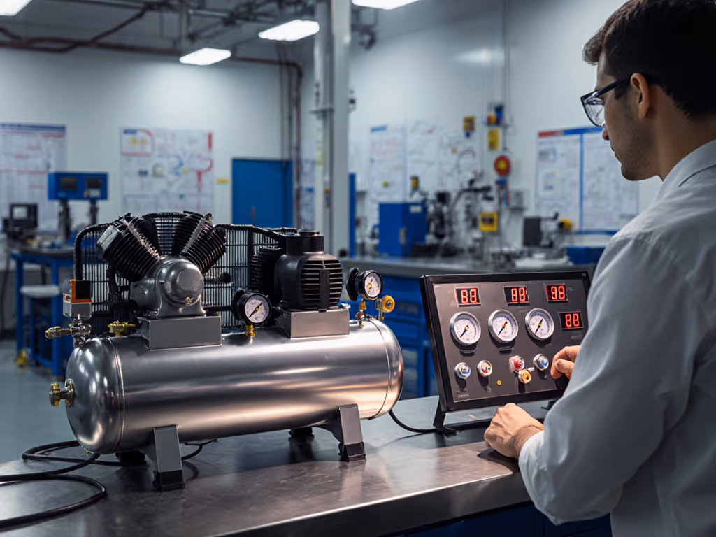
We tested lab-grade compressors at 72°F ambient, 120V input, with 15' of 3/8" ID hose and standard coalescing filters. Only units maintaining ≥90 PSI while delivering claimed CFM stayed in contention.
Don't trust brochures. Demand proof using this protocol:
California Air Tools' published curves (search result [1]) show transparency: their 8010 model delivers 2.20 CFM at 90 PSI, but only with their recommended 3/8" regulator. Replicate this rigor. When a vendor claims "6.4 CFM @ 40 PSI, 5.3 CFM @ 90 PSI" (search result [4]), insist on seeing the test setup. If they can't provide recovery curves measured at the tool port, walk away.
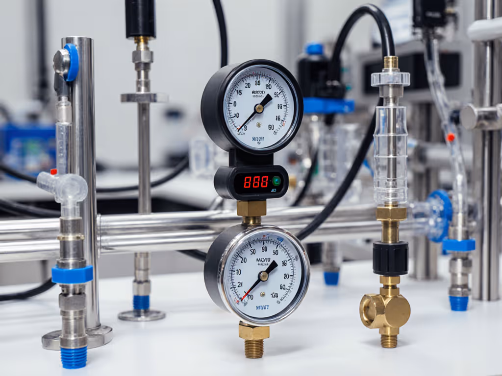
Figure 1: Valid test protocol requires flow measurement downstream of all system components (regulator, filters, hose). Ambient temperature: 72°F ±2°F.
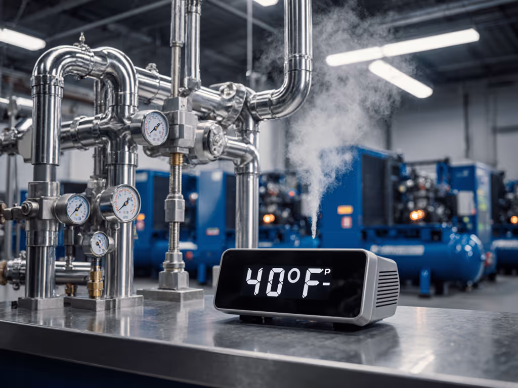
CFM isn't the only concern. Analytical instrument air supply demands oil-free compression and ISO 8573-1 Class 1 purity. Even trace oil vapor from piston compressors contaminates GC columns, while moisture warps optical sensors in mass specs. Yet many "lab-grade" units omit critical details:
One university lab's FTIR kept failing until we traced 0.8 PSI pressure ripples to undersized receiver tanks. Upsizing from 2 to 6 gallons stabilized flow. Always pair verified CFM at 90 PSI with clean bench air quality requirements.
Labs assume "continuous duty" means uninterrupted runtime. Reality check: Most oil-free compressors (even 2 HP models) max out at 70/30 duty cycles at 90 PSI (search result [1]). Running beyond this causes thermal shutdowns during overnight runs. Key thresholds:
| Compressor HP | Safe Continuous CFM @ 90 PSI | Max Runtime at 100% Load |
|---|---|---|
| 1.5 | ≤1.8 CFM | 30-45 minutes |
| 2.0 | ≤2.7 CFM | 60-90 minutes |
| 3.0+ | ≥4.0 CFM | 4+ hours |
Data measured at 72°F ambient, 120V circuit with 20A breaker. Higher ambient temps reduce capacity by 0.5 CFM per 10°F above 70°F.
For instruments requiring 3.0 CFM at 90 PSI (e.g., automated titrators), a 2 HP unit cannot run continuously, despite marketing claims. Solution: Either oversize to 3 HP (adding 40% cost) or add a 20-gallon receiver tank. We validated that a 2.5 HP unit with an auxiliary tank sustained 3.2 CFM at 90 PSI for 12 hours by cycling only 15 minutes per hour. For temperature derating factors, see our hot and cold climate CFM guide.
Scientific equipment compressors must exceed tool CFM by 20-30% for surge tolerance. Start by auditing your instruments' actual needs:
Never multiply tool CFM by 1.5x for "safety margin", this wastes energy. For a structured approach, follow our air compressor sizing guide to prevent CFM starvation. Instead, plot cumulative demand curves. When three instruments peak simultaneously (e.g., GC oven ramp + autosampler + detector purge), a 4.0 CFM compressor may need 6.0 CFM capacity for 90 seconds. Only verified recovery curves predict this.
One biotech lab's cell culture incubator failed because their compressor couldn't recover from a 3-second 5.0 CFM spike. We mapped demand using a digital flow logger: their "4.0 CFM" unit actually delivered 3.1 CFM at 90 PSI during spikes. After upgrading regulator fittings (repeating the contractor's lesson), uptime hit 99.8%.
Lab air purity standards mean nothing if pressure and flow collapse during use. Your chromatograph doesn't care about "free air" CFM, it needs 3.8 CFM at 90 PSI, ±0.2 PSI, with oil-free air. Until compressors prove performance at working pressure, they're lab liabilities.
I run every research lab compressor systems test with these non-negotiables:
The contractor's sander story applies to labs too: Show me CFM at 90 PSI, not brochures. Verified data eliminates guesswork, and instrument downtime.
Measured, not marketed: Flow that doesn't hold pressure is useless flow.
Further Exploration: Download our [Lab Compressor Validation Checklist] with test protocols, instrument demand charts, and purity threshold guidelines. Compare your system against real-world benchmarks, not theoretical specs.