Compressor Intake Filtration for Dusty Shop Particulate Control
17th Sep•9 min read
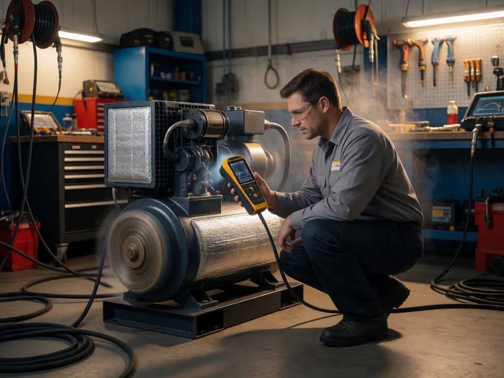
A compressor’s overall dB(A) value cannot show whether the dominant problem is tonal airborne noise, pipe pulsation, or structure-borne vibration. Use the operating condition in which the complaint occurs, compare frequency peaks with machine speed and location, and treat each pattern as a diagnostic lead—not proof of a fault.
Important: There is no universal normal vibration number or frequency-to-fault diagnosis.
Compressor noise spectra and air compressor frequency analysis give you a better starting point than a single dB(A) number when a compressor becomes irritating, starts shaking its plumbing, or suddenly sounds different. The job is not to guess at a fault from a noise label. It is to separate what you hear in the air from what the machine is sending into its frame, mounts, tank, and piping, then compare the frequency pattern with the operating condition.
An overall level alone does not show whether a tonal peak is present. Another compressor can sound broadly mechanical but make the floor, guard, or hard pipe buzz. Those are different sound profiles, and they call for different inspections.
A peak is a lead to investigate, not a diagnosis by itself.
Start by writing down exactly when the objectionable noise occurs. Check the frequency pattern under the operating condition in which the complaint occurs.
Use this short field log:
Do not call every steady hum "electrical." For practical acoustic diagnosis, use tonal hum to mean a prominent airborne tonal peak. Its cause still needs corroboration.
In one screw-compressor installation, tonal frequency varied with changes in speed, load, and temperature. Record the operating condition in which the objectionable sound occurs rather than assuming that a peak is fixed.
Troubleshooting goes sideways when different quantities are treated as though they are interchangeable. They are not.
An overall dB(A) reading can be useful for a broad comparison, but it does not display spectral shape. In listening tests of air-to-air heat-pump recordings, researchers reported that low-frequency noise and tonality may help explain perceived annoyance better than A-weighted level alone. Spectral shape therefore provides information that an overall dB(A) number does not display.

When interpreting trends, account for operating condition, measurement location, direction for vibration monitoring, and setup rather than comparing unlike measurements. Do not treat a sound-pressure spectrum measured at a microphone position as interchangeable with a sound-power rating.
For field screening, note whether a frequency peak stands out from nearby content. In the shop, a tonal complaint may be the sound you can hum back after the compressor has stopped.
A peak that moves as operating speed, load, or temperature changes is worth relating to known machine excitations. In a documented oil-free screw-compressor case, near-field analysis linked an annoying 950 Hz tone to a harmonic of lobe-meshing frequency. That example is not a universal compressor frequency; it demonstrates the method: connect the measured peak to the machine’s actual kinematics before choosing a remedy.
Pressure pulsation can also matter. In positive-displacement compressor work, higher-frequency pulsation can radiate as tonal noise. For reciprocating equipment, pulsations are pressure fluctuations that travel through the piping system. Training material on reciprocating-compressor piping states that the piping system can amplify the issue when excitation overlaps an acoustic resonance.
If those answers line up, investigate the airborne path and the compressor-plus-piping system. Avoid treating a generic enclosure change as a cure until you know where the peak is strongest and when it occurs. A targeted acoustic change can dramatically reduce a peak without producing the same-sized change in overall level; those are separate results.
Vibration resonance is not simply "too much vibration." It occurs when a machine excitation lands near a natural frequency of the supporting structure, allowing a modest input to create a much larger structural response.
The practical clue is location and direction. A vibration peak that is disproportionately large on the frame, a mounting point, or one side of the package points you toward the structure as well as the compressor. In one screw-compressor case, a 48.7 Hz motor-speed excitation sat near a 50 Hz frame resonance. Damping between the motor and frame reduced the frame vibration in that specific installation.
Rotating-machine case work provides useful (but not conclusive) pattern leads:
Machine configuration, measurement location, and hands-on inspection decide whether any of those leads are true. Manufacturer troubleshooting guidance also points to basics that deserve inspection: mounting bolts and brackets, belt tension, flywheels, bearings, enclosure fit, uneven support, and vibration transferred from adjacent equipment.
This is the fork that saves wasted work.
If a reciprocating compressor’s pipe run visibly shakes or a particular section gets loud, do not stop at the pump. For reciprocating equipment, pulsation travels through piping, and excessive pulsation can produce shaking forces, vibration, fatigue-related problems, and noise. Training material on reciprocating-compressor piping states that excitation overlapping an acoustic resonance can produce excessive pulsation, so the piping system can be part of the problem.
If the frame, feet, or mounting structure shows the strongest response, prioritize support conditions and structural resonance. For a broader look at compressor room vibration control, review how room layout, mounting, and surrounding structures influence transmission. If the airborne tone is strongest near a discharge route while frame vibration is modest, prioritize the acoustic and pulsation path.
These mechanisms can coexist. That is why an orderly comparison beats replacing parts on sound alone.
Switch the compressor off before inspection. Detailed safety steps depend on the manufacturer’s and site’s applicable instructions.
Work through the simplest confirmed condition first:
Carry the simple items that make a confirmed repair stick: appropriate mounting hardware, standard service parts specified for the machine, and the records needed to restore your reference condition. Spare parts keep jobs moving.
Regular vibration spectra can be compared with a reference spectrum to help detect changes. For related upkeep planning, see the air compressor maintenance schedule. Interpret changed patterns with the machine configuration, measurement location, and physical inspection in mind. Compare peak frequency, amplitude, direction, and location—not just a single overall number.
Do not use a generic pass/fail vibration number for every compressor. Reciprocating and positive-displacement rotary compressors require machine-specific context, operating conditions, measurement method, and applicable manufacturer limits or standards. A comparison with a relevant reference spectrum is often more actionable than a borrowed number from another machine.
There is no single defensible "normal" number for all compressors. The meaningful limit depends on machine-specific context, measurement conditions, and the applicable manufacturer documentation or machine-specific standard. Compare vibration spectra with a reference spectrum, then interpret any changed pattern in light of the machine configuration, measurement location, and physical inspection.
Run the compressor in the exact condition that produces the complaint. Record the location, operating state, sound character, and whether the strongest response is airborne, in the pipework, or in the structure. Then compare frequency peaks and physical inspection findings before changing parts. Use those comparisons to identify which mechanism and transmission path to investigate first.