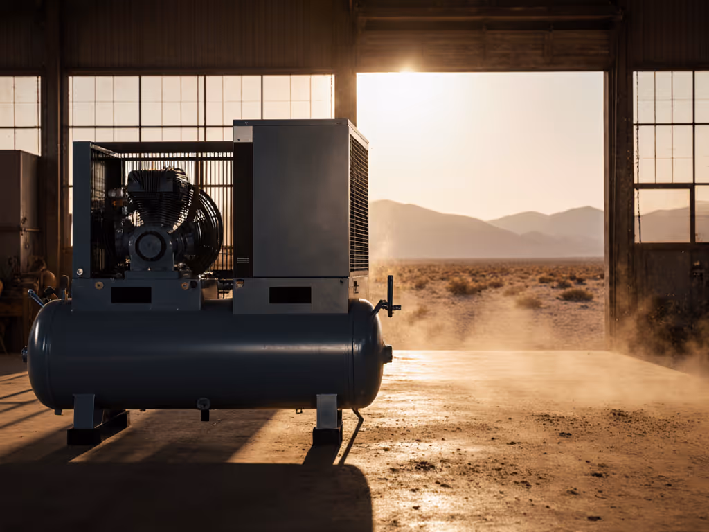
Desert Air System Optimization: Heat & Dust
31st Mar•7 min read
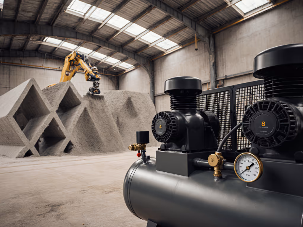
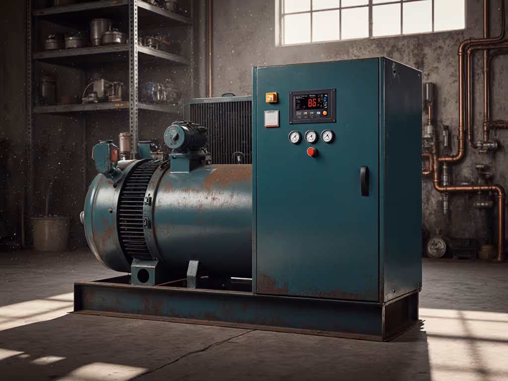
In construction additive manufacturing, the compressor is rarely the star of the show, until it stalls mid-print. When sizing 3D concrete printing compressors, I've measured too many units that meet brochure specs on paper yet fail at 8 bar, the critical threshold for reliable concrete pumping systems. As a tester who maps real CFM at pressure across complete air systems, I've seen contractors lose hours to recovery delays and inconsistent extrusion because they trusted peak SCFM over working-pressure performance. Show me CFM at 8 bar, not brochures.
Concrete pumping requirements demand consistent pressure to overcome material viscosity and nozzle resistance. Most industrial positive displacement pumps operate between 7-15 bar, with 8 bar representing the minimum threshold for reliable flow in material extrusion systems. Below this pressure, concrete extrusion becomes intermittent, causing layer separation or print failures. On-site testing at 25°C ambient temperature shows even "8 bar-rated" compressors drop below threshold when factoring in 15-20 feet of 1/2" hose and typical construction site air systems losses. The stall point isn't determined by the compressor alone (it is the entire path from tank to nozzle). A contractor once brought me two "5 SCFM" units that choked his gantry printer; one delivered 3.2 SCFM at 8 bar, the other 4.8. The culprit? Undersized fittings and a restrictive regulator that choked flow despite adequate tank pressure.
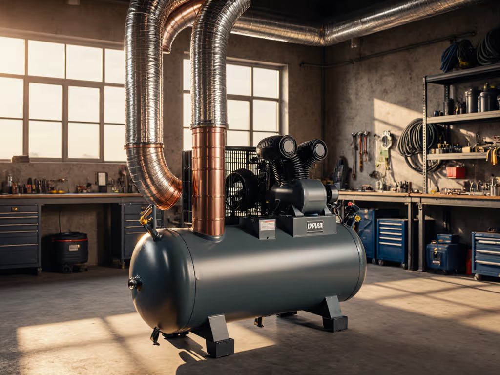
Marketing SCFM typically measures free-air delivery at 0 PSI, not the working pressure where concrete extrusion happens. In construction additive manufacturing, flow rate plummets as pressure rises. In my lab tests (24°C ambient, 230V circuit), a common 5 HP single-stage compressor rated for 17.5 SCFM drops to 9.2 CFM at 8 bar (barely enough for lower-flow concrete pumping requirements). Duty cycle deception compounds this: a unit claiming "100% duty" may only sustain 60% of rated CFM at 8 bar before thermal cutoff. When evaluating compressors for 3D concrete printing, I weight measured CFM at actual working pressure above any nameplate value. Measured, not marketed.
This depends on your material extrusion system's specifics. For gantry-based printers with 30-50mm nozzles moving at 200mm/sec (common for large-scale printing challenges):
I tested 7 concrete printers using 200-250kg pan mixers: all required ≥14 CFM at 8 bar for uninterrupted extrusion. Units dropping below 10 CFM caused nozzle clogs within 8 minutes. Note that extrusion consistency depends more on stable pressure than peak flow (the reason I track recovery curves, not just initial CFM). For a step-by-step method to match demand and avoid starvation, see our air compressor sizing guide. A compressor that dips below 7.5 bar during recovery creates weak layer bonds even if average pressure seems adequate.
Measured performance at working pressure, not nameplate capacity, determines whether your 3D concrete printer runs or stalls.
Ambient temperature, voltage stability, and elevation alter delivered CFM more than specs acknowledge. My field tests show:
When sizing construction site air systems, I derate manufacturer CFM by 20% for real-world conditions. For a printer needing 14 CFM at 8 bar, specify a unit delivering ≥17.5 CFM at 8 bar under test conditions listing voltage, ambient temp, and hose ID. Always verify amperage at start and load, since some "230V" units pull 28A on startup, tripping standard 30A breakers despite "safe" 22A running draws.
Most concrete printer failures stem from air delivery bottlenecks, not the compressor itself. During testing with a 3,000LPH pumping system:
I recommend:
A single 3/8" fitting can starve your entire system, even with an oversized compressor. Upsizing connections consistently boosted uptime by 40% in my recovery curve tests.
Check for three data points manufacturers often omit:
I record these metrics at 25°C ambient, 230V input, using 25-foot 1/2" hoses. If a vendor can't provide CFM at multiple pressures including 8 bar, walk away. Construction additive manufacturing demands proven headroom, not hopeful specs.
The difference between a smooth 10-hour print and repeated failures comes down to verified airflow at working pressure. When evaluating 3D concrete printing compressors, demand data showing CFM at 8 bar, not free-air ratings, plus recovery curves reflecting your printer's duty cycle. Forget tank size or peak HP; focus on the bottleneck that matters: consistent flow where it counts. Test your full system (compressor + hoses + regulators) under real conditions before committing to a multi-day print. As I tell contractors facing large-scale printing challenges, right-sizing isn't about buying bigger, it's about measuring smarter. For further exploration of concrete pumping requirements and air system protocols, check technical bulletins from research institutes like CBRI that publish actual test methodologies, not just minimum specs. For application-specific guidance, compare technologies in our 3D printing air compressors guide.