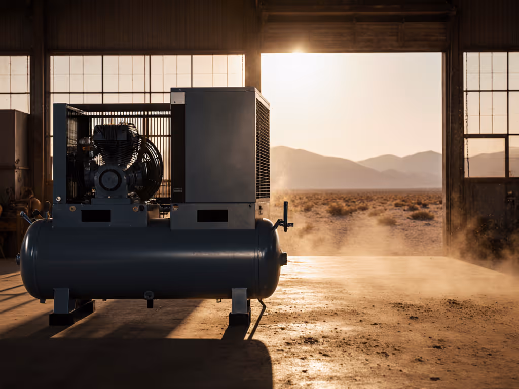
Desert Air System Optimization: Heat & Dust
31st Mar•7 min read
When your spray gun delivers orange peel instead of glass-smooth finishes, or your impact wrench loses torque mid-job, air compressor troubleshooting becomes more than a chore (it is the difference between profit and rework). Most common compressor problems originate not from the compressor itself, but from overlooked pressure drops, moisture, and system imbalances between tank and tool. Finish quality is a system result: clean, dry, and stable pressure beat guesswork every time.
As a spray finishing specialist who's watched countless shops chase phantom "paint issues," I've seen 90% of failures stem from undiagnosed pressure loss at the point of application. Let's cut through the noise with a field-tested diagnostic sequence that targets the actual culprits, not just the symptoms.
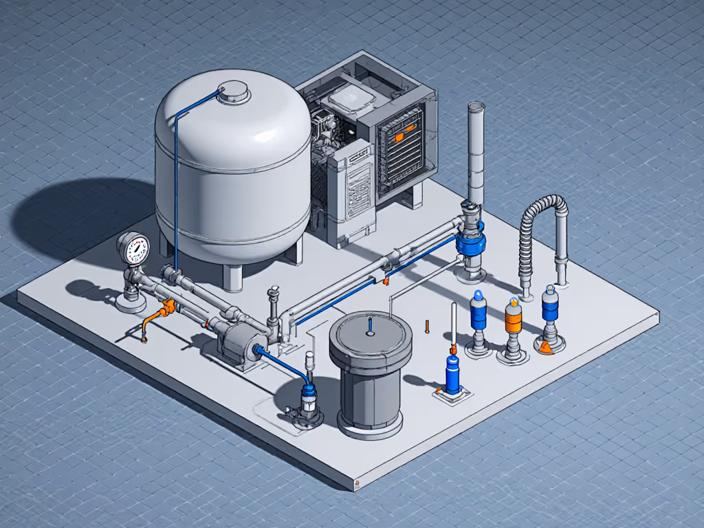
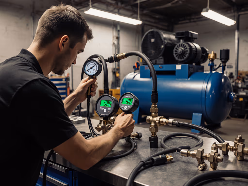
Most technicians check pressure at the compressor tank gauge, then call it a day. But pressure measured at the tank rarely matches what your tool receives. In one case, a body shop battled persistent fish-eyes, blaming the paint supplier. We measured 100 psi at the tank, but just 28 psi at the spray gun trigger. Those missing 72 psi vaporized their finish quality.
Dry air, fewer defects.
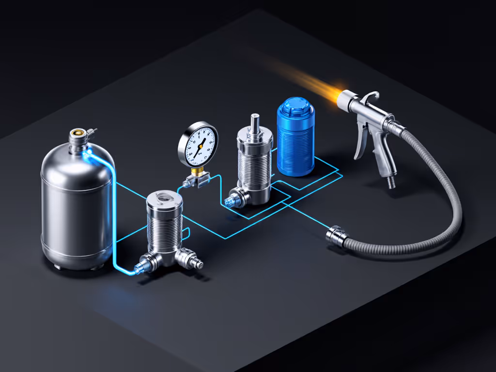
A 3/8" hose reduces pressure drop by 50% compared to 1/4" at 25 CFM. If your regulator sits at the compressor instead of the tool, you're compensating for losses that already occurred (like trying to fix a leaky bucket by adding more water at the source).
Leak detection isn't about finding any leak (it is about prioritizing leaks that impact your workflow). A 1/16" hole wastes 3.5 CFM at 100 psi, but many shops waste hours hunting negligible leaks while missing critical ones in pressurized lines.
Document each leak location with estimated CFM loss. A single faulty quick disconnect might waste 8 CFM, enough to starve an HVLP gun drawing 12 CFM at 40 PSI. This is where targeted air leak detection transforms guesswork into quantifiable repair priorities.
"Low pressure" usually means "insufficient flow at working pressure," a critical distinction. Your compressor might deliver 150 PSI but still starve tools if airflow collapses under demand. For a clear breakdown of CFM and PSI at working pressure, see our CFM vs PSI guide.
100°F indicates fouled heat exchange (common in oil-lubricated units)
This systematic approach to low pressure issues reveals why many shops install oversized compressors yet still face performance gaps, because their filtration stage creates hidden pressure loss. Clean, dry, stable air makes finishes look inevitable.
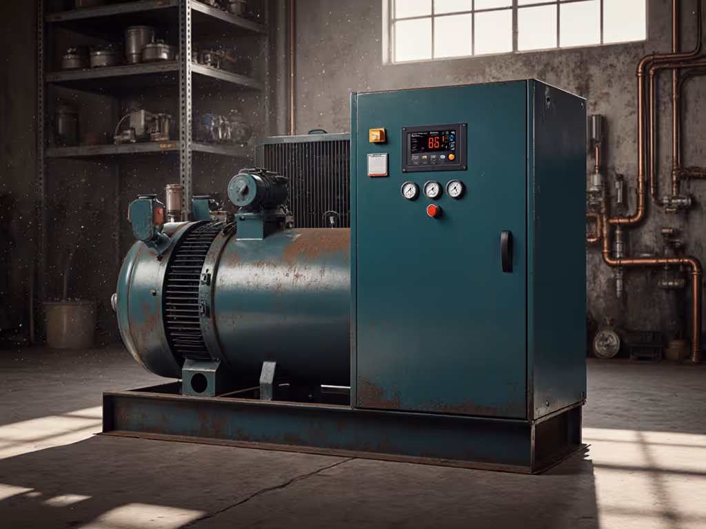
When a compressor won't start, 80% of shops immediately check power and oil, critical first steps, but rarely the full story. Thermal overload trips often signal deeper system imbalances.
80°F ambient requires 20% CFM derating
70% RH increases moisture load by 35%
This data-driven approach to compressor won't start scenarios prevents misdiagnosis. One mobile detailing rig kept tripping thermal overload, not from motor issues, but because their 50-foot hose created 18 PSI backpressure during startup.
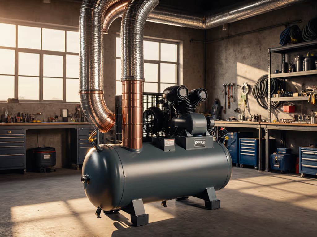
"Overheating" is not a single problem (it is three distinct failure modes requiring different overheating solutions).
| Symptom | Likely Cause | Quantitative Fix |
|---|---|---|
| Gradual temp rise during operation | Insufficient cooling airflow | Maintain 300+ CFM cooling per HP; verify 18" clearance around unit |
| Sudden shutdown at consistent intervals | Moisture overload in aftercooler | Install 35°F dew point dryer; verify drain cycle frequency |
| High discharge temp but normal oil temp | Plugged intercooler (two-stage) | Clean fins with compressed air; replace if pressure drop >12 PSI |
Never address symptoms alone. One framing contractor's compressor kept overheating at 102°F ambient, until we discovered their 1/4" intake hose created 8" H₂O restriction, reducing volumetric efficiency by 22%. Ambient temperature matters, but system design matters more.
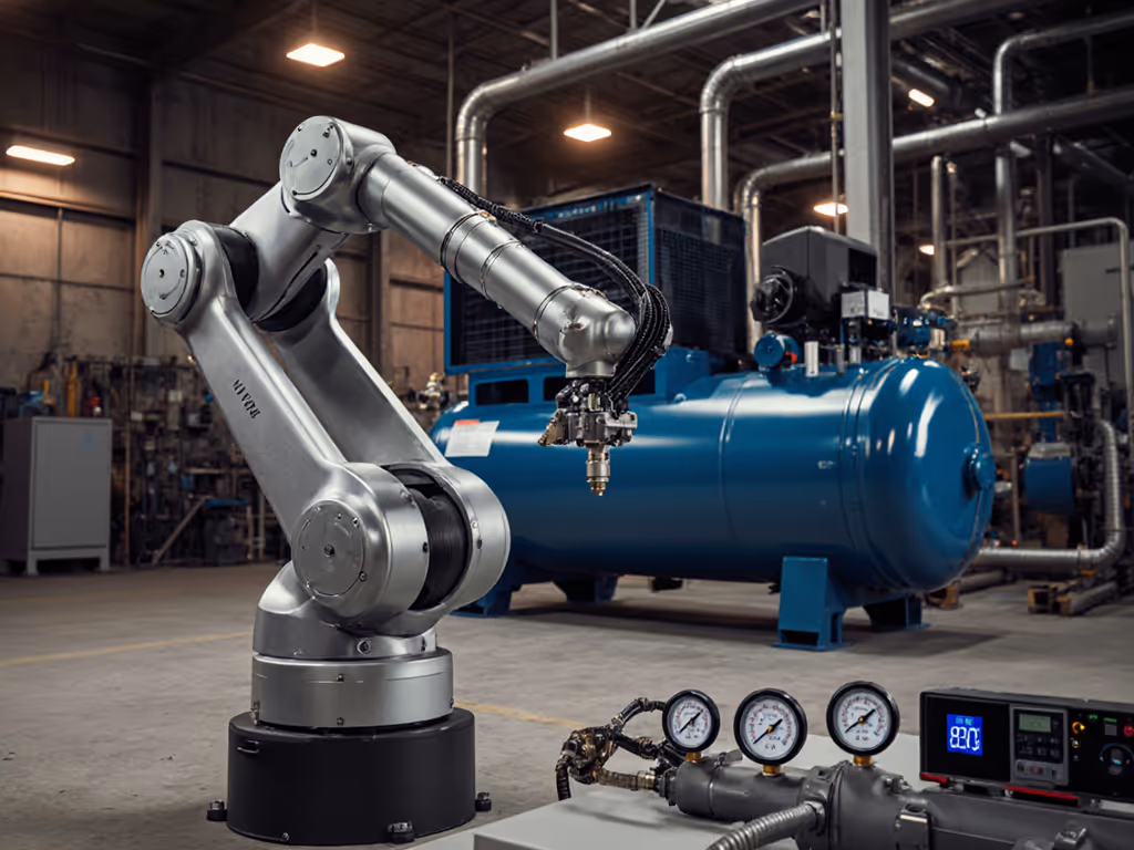
Effective air compressor troubleshooting requires treating your compressed air system as an integrated circuit, not a collection of isolated components. When pressure drops murder your finish quality or tool performance, you're seeing symptoms of upstream failures.
Start at the tool, measure actual working conditions, and work backward through each treatment stage. Document pressure, flow, and dew point at every transition point. The data will reveal where your system leaks performance, often in places you never suspected.
For shops serious about eliminating guesswork, I've developed a free Pressure Mapping Worksheet that walks you through each measurement point with industry-standard tolerances. It's saved countless painters from blaming their paint when the real culprit was wet air and unstable pressure. Because, at the end of the day, dry air means fewer defects, and that is a finish any professional can be proud of.