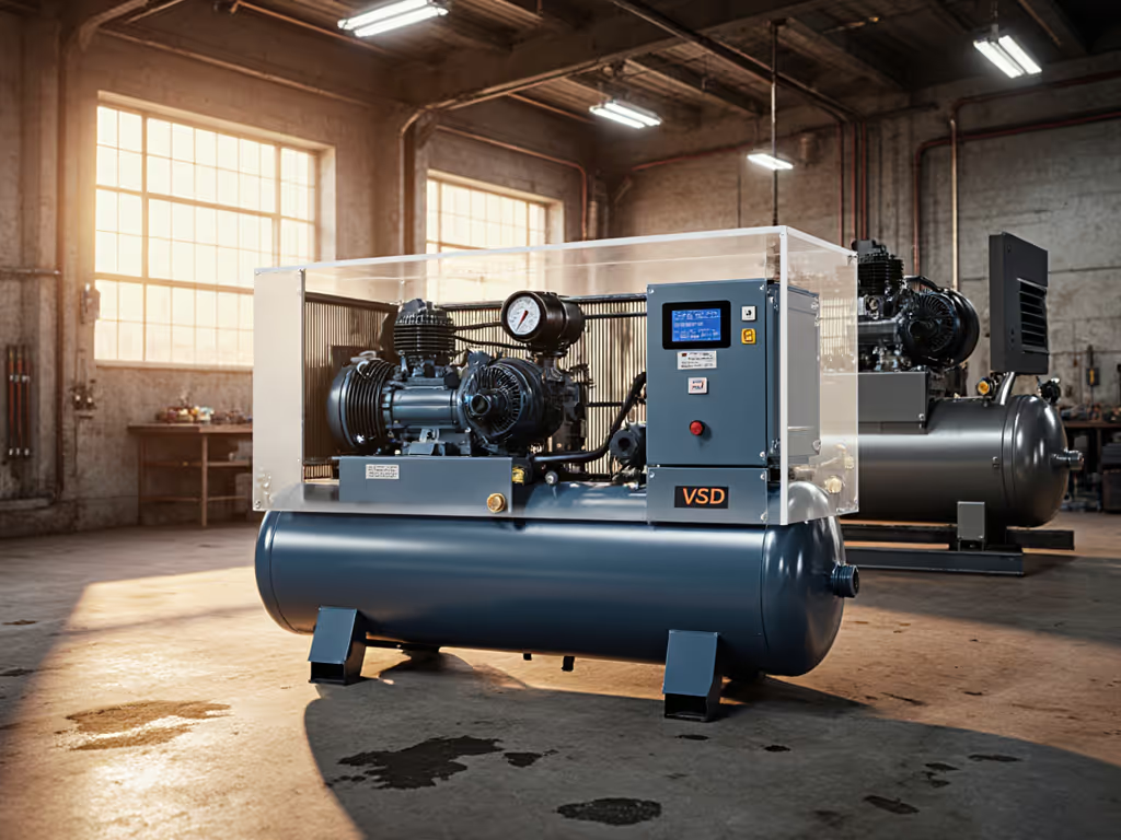
Compressor Technology Evolution: From Pistons to VSD Systems
3rd Feb•6 min read
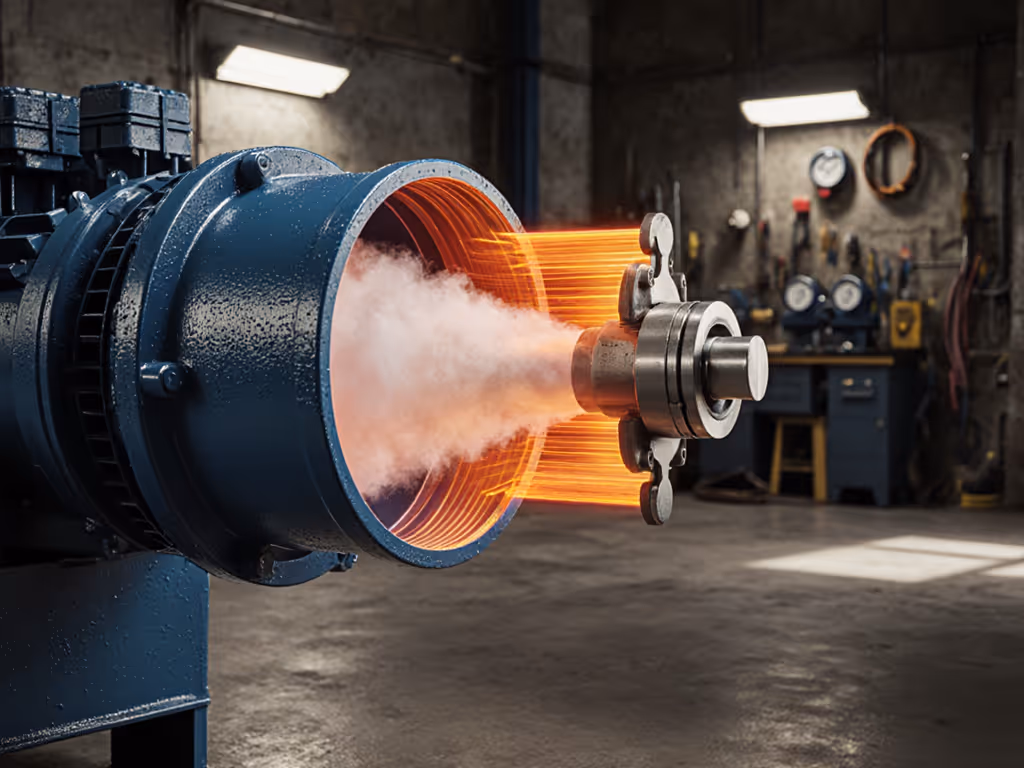
When you squeeze air, it gets hot. That principle (the behavior of adiabatic compression in industrial compressors) is fundamental to why your shop feels warm after running tools, why pump heads swell, and why managing thermal output isn't an afterthought but a system requirement. This guide unpacks the physics and practical implications in language that matches how you actually work.
When a gas is compressed adiabatically, no heat transfers out of the system, so all the work done on the gas raises its internal energy, and therefore its temperature. Think of it like pumping air into a tire: the pump body gets warm, not because of friction alone, but because the air itself is being energetically compressed into a smaller space. For a quick refresher on components and fundamentals, see how air compressors work.
In an ideal adiabatic process, the relationship between temperature and volume follows a precise path:
T × V^(γ-1) = constant
Here, γ (gamma) is the heat capacity ratio, roughly 1.4 for air at ambient conditions. If you know the starting temperature and the volume ratio (or pressure ratio) during compression, you can calculate the exit temperature. The steeper the compression, the hotter the result.
An ideal adiabatic process assumes no friction and perfect insulation. Real industrial compressors deviate because:
These real-world losses mean the process is polytropic, not truly adiabatic. A polytropic process sits between adiabatic (no heat transfer) and isothermal (constant temperature): some heat escapes, but not all. Accounting for this means using a polytropic exponent n instead of the ideal γ, which is essential for predicting actual discharge temperatures.
For a typical oil-lubricated two-stage compressor running at modest pressure (90 PSI), discharge temperature can reach 250-300°F in the head before cooling. Neglect this, and you risk thermal shutdowns, oil degradation, and premature seal failure.
Isentropic efficiency is a benchmark that compares real compressor work to the theoretical minimum (isentropic, or reversible adiabatic, work). The ratio reveals how much energy is wasted:
Isentropic Efficiency (%) = (Ideal adiabatic work) / (Actual work input) × 100
A well-designed, clean single-stage compressor achieves 70-80% isentropic efficiency. Two-stage designs typically reach 75-85%. Oil-free models often run 60-75%, since the absence of lubrication oil increases friction losses. If your electric bill is climbing and air output isn't, poor efficiency is often the culprit: a compressor working harder to move the same air volume means wasted power (and more heat). To reduce waste under variable loads, compare VSD vs fixed speed compressors.
If you know the inlet temperature, pressure ratio, and polytropic exponent, temperature rise calculations follow this formula:
T₂ = T₁ × (P₂ / P₁)^((n-1)/n)
Where:
Example: Assume inlet air at 68°F (20°C = 293 K), compressed from 14.7 PSIA (1 bar absolute) to 90 PSIG (6.2 bar absolute), with n = 1.25.
T₂ = 293 × (6.2 / 1.0)^((1.25-1)/1.25) = 293 × 6.2^(0.2) ≈ 293 × 1.45 ≈ 425 K ≈ 160°C (320°F)
Your discharge temperature just climbed nearly 250°F above ambient. Without an aftercooler or adequate tank dwell time, that hot air causes condensation issues downstream and stresses seals and hose inner tubes.
Temperature rise isn't academic. I worked with a cabinet shop that treated noise and heat as inevitable costs of business. The compressor (a modest piston unit) ran inside a utility closet with no ventilation, fed by a crumpled intake line and exhausted straight into the shop. Discharge temperature climbed to 280°F within an hour, triggering thermal shutdowns every 45 minutes. The pump overheated, the oil broke down faster, and the shop sat waiting.
We relocated the compressor into a ventilated closet, floated it on isolation pads to decouple vibration, ducted a lined intake from outside, and routed the exhaust through a check valve and muffler back out. We also installed an automatic drain valve on the tank. For layout and airflow best practices, see our compressor room design guide. Measured dBA dropped by 12 at 1 meter, and the thermal issue vanished. Discharge temperature peaked at 220°F, recovery was crisp, and conversations returned. The shop's duty cycle became continuous, errors fell, and finish rework quietly followed.
The lesson: thermal management and heat transfer in compressors are inseparable from system design. Cooling clearance, airflow path, and mounting all matter.
Higher pressure ratios mean larger temperature rises. At 90 PSIG, your ratio is 6.2:1. At 175 PSIG, it's 12:1. The temperature scales non-linearly (roughly as the 0.2 power of the pressure ratio for air). That's why deep pressure tools (sandblasters, tire filling) demand bigger, cooler systems or multi-stage designs that spread the compression across two cylinders, each with a lower ratio and intermediate cooling.
Quiet isn't luxury; it's throughput and focus you can hear. When your compressor runs cool and quiet, your shop runs smoother, tools respond instantly, and you finish before fatigue sets in.
To refine your system, measure your actual air demand at working pressure (CFM at 90 PSI, not just peak SCFM), log tank pressure and recovery time over a typical task cycle, and compare discharge temperature before and after adding an aftercooler. For spec clarity, use our CFM vs PSI guide to interpret real airflow at 90 PSI and avoid marketing traps. Record noise at 1 meter and note the frequency where you hear harshness most (often 250-500 Hz in piston units). These data points are your foundation for matching compressor type, tank size, cooler capacity, and isolation strategy to your specific work. Standardized tests under consistent conditions reveal truth; vendor datasheets alone do not.